March 8, 2008
Arduino showing multiplexed LED matrix
Posted in: Art, Gadgets, Software, TechTo control any more than 12 LEDs on an Arduino board requires a bit of trickery. The Diecimila with its Atmega168 chip has 14 digital output pins, but you somewhat lose two from the TX/RX serial pins on 0 and 1 leaving just 12 pins. Today I built an LED matrix with 20 lights using nine pins,
The technique is to light row by row, and rely on our persistence of vision effect. Playing around with the delay it seemed like 3ms for a total of 15ms (five rows) was about the point where flicker just started being noticeable.
Geeky detail after the fold...
The software pulls the row pins high one by one while the column pins are set low for every LED to light, sinking the current from the one high row pin. There's a 3ms delay, then the next row pin is brought high and the last one low.
The data for the little animation is a 2D byte array that looks like,
byte PATTERN[][5] = {
  /* ... */
  {B0111,
   B1110,
   B1100,
   B1000,
   B0000,},
  /* ... */
};
('B' is a handy prefix for a binary number.)
You can see a diagonal band of 1's there in the early part of the wipe. Each byte's translated into pin writes by looking at the lowest bit in the byte and then shifting right and looking at the next. LOW is on.
void SetColumn(byte pattern) {
  for (int i = COL_COUNT-1; i >= 0; i--, pattern >>= 1) {
    digitalWrite(COL_PINS[i], pattern & 1 ? LOW : HIGH);
  }
}
A "frame" of the display is completed by lighting each row in turn,
void ShowPattern(byte pattern[]) {
  int last_row = ROW_COUNT-1;
  for (int row = 0; row < ROW_COUNT; last_row = row++) {
    digitalWrite(ROW_PINS[row], HIGH);
    digitalWrite(ROW_PINS[last_row], LOW);
    SetColumn(pattern[row]);
    delay(MULTIPLEX_DELAY_MS);
  }
}
The main loop draws each frame over and over until a certain amount of time has elapsed and then it goes onto the next one. millis() is a built-in that returns the number of milliseconds since the board was switched on. (This code would fail after about nine hours when the counter resets.)
void loop()
{
  for (int pos = 0; pos < PATTERN_SIZE; pos++) {
    long start = millis();
    while (millis() - start < PATTERN_DELAY_MS) {
      ShowPattern(PATTERN[pos]);
    }
  }
}
Notes
I actually had the circuit the other way around, cycling through column-by-column and the rows programmed in turn with a line of lights. This happened out to make writing patterns awkward so I flipped the orientation which made SetColumn pretty straightforward.
The matrix could've had more lights on it but the breadboard limited width a bit. I was quite proud of the tight wiring under the LEDS.
| From Multiplexed LED Matrix |
This was one of the projects where the bits that seemed like they'd be hard Just Worked and then silly things wasted time, like C mistakes with sizeof.
int ROW_PINS[] = {13, 12, 11, 10, 9};
int COL_PINS[] = {5, 4, 3, 2};
#define ROW_COUNT (sizeof(ROW_PINS)/sizeof(ROW_PINS[0]))
#define COL_COUNT (sizeof(COL_PINS)/sizeof(COL_PINS[0]))
Parameterizing these kinds of things made moving from a 3x4 board to 4x5, flipping the rows & columns, and using different pins trivial. An unfortunate cargo-cult effect in Arduino and Wiring code I've seen is folks not using #define and sizeof.
Some cute enhancements might be to have an array of structs, the struct containing additionally a delay time for each frame. We could also have, rather than 0/1, a wider range of values to indicate brightness. With that, (e.g. Perl/Python scripted) code could generate the animation sequences rapidly flipping frames to give an impression of anti-alias. Unfortunately I have other things to do... (yeah, I made the animations by hand in vi and pasted into the Arduino editor :-))
And finally, a Wiring-based pair of color LED matrixes are used as toilet signs... that change throughout the night [video]. More on this funny project.
March 2, 2008
My first Arduino project
Posted in: Gadgets, Software, Tech, What am I up toI've spent a very pleasant Sunday afternoon playing with an Arduino microcontroller board. After a trip to Maplin I plugged together a little array of assorted LEDs from their "lucky bags" and got hacking.
The Arduino board is fabulous: for an amazingly cheap €22 you get a USB-programmable 16Kb microcontroller with a bunch of digital and analog input and outputs, and the outputs are capable of driving useful things like LEDs. The software's not just free but open source too--and it's decent, with excellent documentation. I'd say from downloading the software and getting my first "hello world" program loaded was about five minutes. It Just Worked™. This might not sound like a big deal, but interfacing to computers has generally been expensive, esoteric, fiddly, and error-prone. The Arduino board is none of these.
The tutorials are great and introduce the important concepts with example circuits and code. In fact, the set of example code is all accessible directly from the Arduino app's main menu, which is a nice touch. (I.e. you don't have to dig around trying to open a file buried on your hard drive.)
So anyway here it is. Eleven LEDs connected to digital pins 0-10, and a 22k linear pot (variable resistor) feeding analog pin 5. The LEDs "chase" up and down with a speed taken from the pot position.
It was fairly painless, at least after an initial scare where programs wouldn't upload,
avrdude: stk500_recv(): programmer is not responding
avrdude: stk500_recv(): programmer is not responding
I read all sorts of scary solutions online where folks were reprogramming their bootloaders and other horrors. One Arduino hacker mentioned running the board off an external power supply (rather than rely on USB) during programming as the current draw is apparently higher. This was enough for me to try pull the LED's ground pin out so the lights turned off: Bingo! No problem programming. It became a bit annoying pulling the ground lead out every program: next trip to Maplin I get a switch...
The other issue I had was remembering how C does casting. My function to scale the analog input into a minimum and maximum delay was being simultaneously confused by my code not casting up to a float early enough, and a persistently dodgy connection with the pot.
(The fifth pin/LED didn't seem to light very strongly. Tried different LEDs and lower resistance. Didn't fix it or figure out why it was dim; I'll try a different board soon.)
So what led me to Arduino? The brand new Science Gallery at Trinity College in Dublin is running a programme to introduce high school kids who wouldn't otherwise have had the educational opportunity to do so to learn about electronics. I'm helping out there on Wednesday afternoons, which so far has mostly involved teaching them how to solder, and debugging electronics problems. Where possible I have them learn from my mistakes: my room in my parents' house, for example, was so badly burnt from soldering iron accidents and riddled with little lumps of solder they had to replace it after I left... (I suppose one useful legacy I left was installing about two dozen plug sockets :-))
So far the kids have created some very cool LED pictures each with a fierce amount of soldering and now are ready to hook them up to Arduinos. Hence the need to stay one step ahead of the younger generation ;-)
If you're curious, here's the code for the LED chasing. It's C with some special built-in functions like setup(), delay(), analogRead(), etc.
#define LED_COUNT 11
#define DELAY_MIN 10
#define DELAY_MAX 400
#define DELAY_STEP 50
#define POT_PIN 5
#define INTERNAL_LED_PIN 13
void setup()
{
  for (int i = 0; i < LED_COUNT; i++) {
    pinMode(i, OUTPUT);
    digitalWrite(i, LOW);
  }
  pinMode(POT_PIN, INPUT);
  pinMode(INTERNAL_LED_PIN, OUTPUT);
}
int ScaleDelay(int in)
/* Calculates a delay between DELAY_{MIN,MAX} from an analogRead.
 */
{
  float d = (DELAY_MAX - DELAY_MIN) * (float)in;
  d = d / 1024 + DELAY_MIN;
  return (int)d;
}
void LightLED(int led_pin, int last)
/* Reads a delay, lights an LED on led_pin; turns off the last one a short time later.
 */
{
  int d = ScaleDelay(analogRead(POT_PIN));
  digitalWrite(led_pin, HIGH);
  delay(d / 10);
  digitalWrite(last, LOW);
  delay(d);
}
#define TAIL_LENGTH 3
int tail[TAIL_LENGTH];
int tail_pos = 0;
int LastLED(int current)
/* Maintains a list of lit LEDs. Returns the very last one.
 */
{
  tail[tail_pos] = current;
  tail_pos = (tail_pos + 1) % TAIL_LENGTH;
  return tail[tail_pos];
}
void loop()
{
  int last;
  for (int i = 0; i < LED_COUNT; ++i) {
    last = LastLED(i);
    LightLED(i, last);
  }
  digitalWrite(INTERNAL_LED_PIN, HIGH);
  for (int i = LED_COUNT-1; i >= 0; --i) {
    last = LastLED(i);
    LightLED(i, last);
  }
  digitalWrite(INTERNAL_LED_PIN, LOW);
}
November 25, 2007
Extended Durex Play (Vibrating Ring)
Posted in: GadgetsI got one of these little vibrating ring doodads and can concur with these reviews that's it's bloody great. There are two problems though. First of all it's €10+ in the Rip-off of Ireland. Compare that with $22 for 6 in the US! And the second is that it's intended to be disposable (20mins of use). The second problem wouldn't be a problem if they were on sale for an American style €2.40 each.
So being the gadgety skinflint that I am, what follows is how to disassemble it and replace the batteries with more powerful ones...
- Wash it :-)
- Pop the device out by squeezing it through the switch hole,
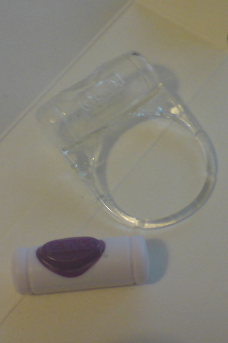
- I took a very sharp unserrated steak knife and sliced into one end,

- Then I took a a thicker, sturdier knife and widened the gap,
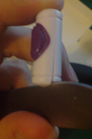
- I flipped back to the skinny knife and extended the gap gutting it like a fish,
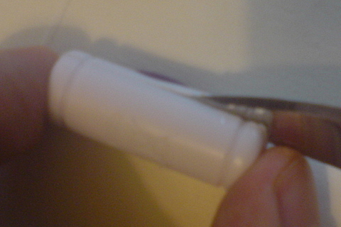
- The skinny knife still in there I brought in the second knife and opened them like scissors popping the device open,
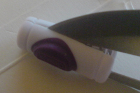
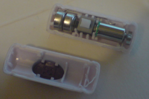
I'd say the device is lightly glued together so there weren't little catches I could pop next time. - So here it is: two little batteries, a motor with a semi-circle of metal, and a switch. Who would've thought?
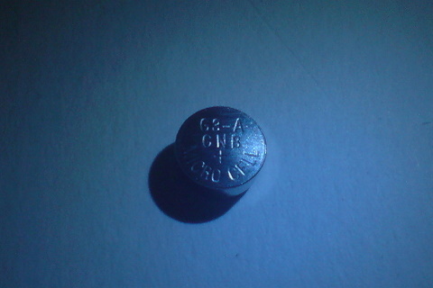
- The battery says G3-A which turns out to be, according to this chart an LR41 aka 192, a 1.5V alkaline button cell. My geeky teenage years and stint working at Maplin put to good use: that battery is the same as a SR41 silver oxide and the SR41 is both higher capacity and higher voltage: more vibrations, and longer!
- Re-assemble. Because the device is sheathed in rubber I'm not worried about insulating it.
Enjoy :-)